
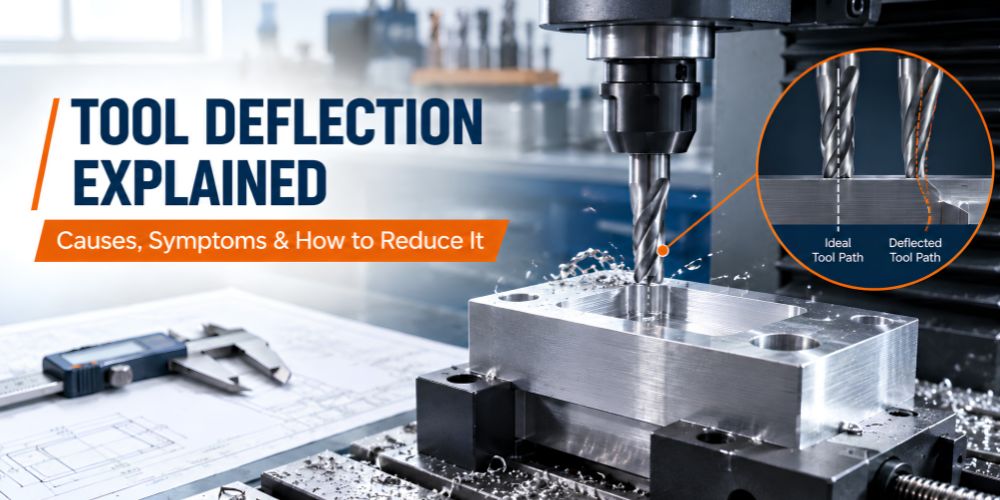
A cutting tool can follow the programmed path correctly and still produce a part that is slightly out of position. During machining, cutting forces can push the tool away from its intended path, especially when the cutter is long, small in diameter, or heavily loaded. This movement can lead to dimensional errors, poor surface finish, vibration, tool wear, and even breakage. Understanding tool deflection helps identify these problems and correct the setup before changing the machine or program unnecessarily.
What Is Tool Deflection?
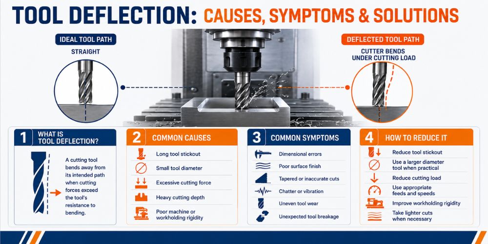
Tool deflection is the bending or displacement of a cutting tool caused by cutting forces during machining. The tool moves away from its intended position as the load increases. Longer tool overhang, smaller tool diameters, heavier cuts, and less rigid setups generally make deflection more noticeable.
Tool deflection is different from runout in machining. Runout is unwanted variation in the rotation of a tool or workpiece, while deflection occurs when cutting forces cause the tool to bend or move during machining.
What Causes Tool Deflection?
Several conditions can increase the load acting on a cutting tool. Understanding these causes makes it easier to choose the right adjustment instead of simply reducing the feed rate.
Cutting Forces
Cutting forces are the main driver of machining deflection. As the amount of material being removed increases, the load on the cutter also increases.
Heavy engagement, aggressive cutting conditions, or difficult-to-machine materials can increase these forces. If the tool is not sufficiently stiff for the load, it can move away from its intended position.
Tool Overhang
Tool overhang is the unsupported length of the cutter extending from the tool holder. As this length increases, the tool becomes more susceptible to bending.
This is particularly important with small-diameter end mills. Keeping the exposed tool length as short as practical is one of the simplest ways to reduce end mill deflection.
Tool Diameter
Tool diameter has a major effect on tool stiffness. A smaller cutter generally has less resistance to bending than a larger cutter of the same unsupported length.
This is why a small end mill can deflect noticeably even when the cutting load seems relatively light. The appropriate tool diameter depends on the operation, available clearance, material, and feature being machined.
Depth and Width of Cut
A deeper or wider cut generally increases cutting engagement and the forces acting on the cutter.
If a tool begins deflecting during a heavy cut, reducing the depth or width of cut can lower the cutting load without necessarily changing the entire machining operation.
Machine, Tool Holding, and Workholding Rigidity
Deflection is not always caused by the cutter alone. The tool holder, spindle, machine structure, and workholding system all contribute to the rigidity of the machining setup.
A securely held tool and workpiece help keep the cutting system stable. Movement anywhere in this chain can reduce machining accuracy.
What Are the Signs of Tool Deflection?
Tool deflection does not always look like obvious bending. It often appears through changes in the finished part or cutting behavior.
Tapered or Inaccurate Walls
When a cutter moves under load, it may not remove material exactly where the programmed toolpath indicates. This can produce tapered walls or dimensions that differ from the intended size.
The effect can be especially noticeable when machining narrow slots, pockets, or walls with small cutters.
Poor Surface Finish
Deflection can change how the cutting edge contacts the material. The resulting variation may leave tool marks, an inconsistent finish, or visible surface irregularities.
If a finish problem persists despite reasonable cutting conditions, checking the tool setup and rigidity can help identify whether deflection is contributing to it.
Chatter or Vibration
Tool movement can contribute to vibration and unstable cutting. If you are also seeing chatter during milling, the issue may involve both tool deflection and the overall rigidity of the setup.
Dimensional Errors
A programmed dimension does not guarantee that the cutter will remain exactly on that path under load. Deflection can shift the effective cutting position and cause the finished feature to be oversized, undersized, or inconsistent.
Premature Tool Wear or Breakage
Uneven loading can increase stress on the cutting edges. In severe cases, this can contribute to chipped edges, accelerated wear, or end mill breakage.
What Is the Difference Between Tool Deflection and Runout?
Tool deflection and runout can both cause machining problems, but they occur for different reasons.
| Feature | Tool Deflection | Runout |
| Main cause | Cutting forces | Rotational variation |
| When it occurs | Under cutting load | During rotation |
| Main effect | Tool displacement | Uneven tool rotation |
| Common results | Dimensional errors, poor finish | Uneven cutting, tool wear |
| Typical check | Evaluate cutting load and tool/setup rigidity | Measure with an indicator |
If uneven rotation is suspected before cutting begins, runout in machining is worth checking separately because it can affect how evenly the cutting edges engage the material.
How Do You Reduce Tool Deflection?
Reducing deflection is mainly about controlling cutting load and improving the stiffness of the complete setup.
Reduce Tool Overhang
Keep the unsupported portion of the cutter as short as the operation allows. A shorter tool overhang increases resistance to bending and usually provides a more stable cutting condition.
Avoid using extra tool length simply because it is available. Extend the cutter only as far as necessary to reach the feature.
Choose an Appropriate Tool Diameter
Use the largest suitable tool diameter that the operation and geometry allow. A larger cutter generally provides greater stiffness, but clearance and feature size still determine what can be used.
For small internal features, a smaller end mill may be unavoidable, so reducing overhang and cutting load becomes even more important.
Reduce Cutting Load
If the cutter is deflecting, consider reducing the depth or width of cut. Lighter engagement reduces the forces acting on the tool and can improve dimensional consistency.
The goal is not simply to make every cut as light as possible. Cutting conditions should match the tool, material, machine, and operation.
Improve Tool Holding
Make sure the cutter is properly seated and securely held. A clean and consistent tool-holding setup helps prevent unwanted movement.
Tool condition also matters. A worn or damaged cutter can behave differently from a sharp, properly seated tool.
Improve Workholding
A tool can appear to be the source of a dimensional problem when the workpiece is actually moving. Check that the part is securely supported and clamped before changing cutting parameters.
Stable workholding helps the entire machining setup respond more predictably to cutting forces.
Use Appropriate Feeds and Speeds
Feed rate and spindle speed influence cutting conditions and the load placed on the tool. Excessive cutting load can increase deflection, while inappropriate settings can also contribute to vibration or poor chip formation.
Check Chip Load
Chip load is another useful factor when troubleshooting cutting forces. If the cutter is removing too much material per tooth, the increased load can contribute to deflection.
Understanding chip load in milling can help when adjusting cutting conditions for smaller tools.
How Can You Quickly Check for Tool Deflection?
When a part shows unexpected dimensional or surface problems, check the setup systematically:
- Is the tool overhang longer than necessary?
- Is the cutter suitable for the material and operation?
- Is the tool diameter too small for the cut?
- Is the depth or width of cut excessive?
- Is the feed rate creating too much cutting load?
- Is the tool securely held?
- Is the workpiece moving?
- Could runout be causing uneven cutting?
Making one change at a time makes it easier to determine which factor is responsible for the problem.
Tool Deflection Troubleshooting Chart
| Symptom | Possible Cause | First Adjustment |
| Tapered walls | Tool bending | Reduce tool overhang |
| Rough finish | Deflection or vibration | Reduce cutting load |
| Cutter vibration | Excessive cutting force | Adjust cutting conditions |
| Dimensional error | Tool movement | Check tool setup |
| End mill breaking | Excessive cutting load | Reduce engagement |
| Uneven cutting | Runout or deflection | Check tool setup |
Why Tool Deflection Matters More With Small Cutters
Small cutters are particularly sensitive to deflection because their smaller diameter provides less stiffness. A long, unsupported small-diameter end mill can move significantly under relatively modest cutting forces.
This matters in small-scale precision machining because even a small change in tool position can affect a narrow wall, slot, pocket, or finished dimension.
For this reason, small-tool machining benefits from short tool overhang, stable workholding, appropriate cutting loads, and careful setup.
How Does Tool Deflection Affect Surface Finish?
Tool deflection changes the position and engagement of the cutting edge as the tool moves through the material. This can create uneven cutting and visible tool marks on the finished surface.
If deflection is not the only suspected cause, other factors such as cutting parameters, tooling, and vibration should also be considered when improving surface finish in milling.
How Does Tool Deflection Affect Machining Accuracy?
Tool deflection creates a difference between the programmed cutter position and the actual position of the tool under load. That difference can affect feature size, wall geometry, and dimensional consistency.
The effect becomes more important when precision machining with micro milling, where small dimensional changes can affect narrow features and finished geometry.
Simple Rules for Reducing Tool Deflection
- Keep tool overhang as short as practical.
- Use the largest suitable tool diameter.
- Avoid unnecessarily heavy cuts.
- Secure the tool properly.
- Check workholding before changing cutting parameters.
- Watch the cutter and chips during machining.
- Treat unexpected dimensional errors as a possible setup issue, not only a programming issue.
Conclusion
Tool deflection is primarily a response to cutting forces acting against the stiffness of the tool and machining setup. Reducing tool overhang, controlling cutting load, and improving tool holding and workholding can help maintain dimensional accuracy and surface quality.
For small precision machining projects, choosing equipment that suits the required part size, material, and machining operation is equally important. TAIG Tools provides small-scale milling and machining equipment designed for precision-focused workshop applications.
Tool Deflection FAQs
What is tool deflection in machining?
Tool deflection is the movement or bending of a cutting tool caused by cutting forces. It can shift the cutter away from its programmed path and contribute to dimensional errors, poor surface finish, vibration, and premature tool wear.
What causes end mill deflection?
End mill deflection is commonly caused by excessive tool overhang, a small tool diameter, high cutting forces, heavy cuts, or insufficient rigidity in the tool-holding and workholding setup.
How do you reduce tool deflection?
Reduce tool overhang, use an appropriate cutter diameter, lower excessive cutting engagement, and improve tool and workholding rigidity. Adjusting cutting conditions can also reduce the forces acting on the tool.
Does tool diameter affect deflection?
Yes. Smaller-diameter tools generally have less resistance to bending than larger tools. When a small cutter is required, keeping the tool overhang short and controlling cutting load becomes especially important.
Does tool length affect deflection?
Yes. Longer unsupported tool length increases the cutter’s susceptibility to bending. Keeping the tool extension as short as practical can improve stiffness and reduce movement during cutting.
Can tool deflection cause chatter?
Tool deflection can contribute to unstable cutting and vibration, but chatter has multiple possible causes. Machine rigidity, workholding, tooling, and cutting conditions should also be checked.
Can tool deflection affect surface finish?
Yes. Tool movement can change cutting-edge engagement and produce uneven cutting, tool marks, and inconsistent surface finish.
What is the difference between runout and tool deflection?
Runout is variation in the rotation of a tool or workpiece, while tool deflection is movement caused by cutting forces. Both can affect machining results, but they require different troubleshooting approaches.
